 Architrave Journal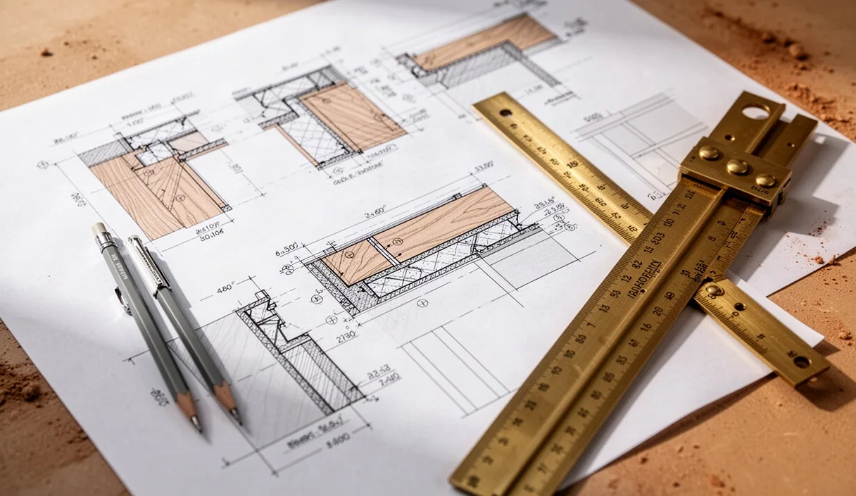
A drafting office routinely risks friction when its drawings presume to understand timber better than the workshop does. Structural specification sheets for contract and bespoke furniture must bridge two distinct modes of thinking: the geometric idealism of architectural design software and the variable, anisotropic nature of seasoned wood under atmospheric load. When a spec sheet relies on generic notes such as "construct per standard millwork practices," it abdicates design authority and invites inconsistencies in fabrication, dimensional failure across changing seasons, and expensive rework during site installation.
A rigorous specification sheet is not an illustration; it is an unambiguous technical instruction and a quality control contract. It defines geometry down to millimetric tolerances, establishes datum lines from which critical clearances derive, and dictates how moisture movement, fastener mechanics, and core compositions interact over decades of service. Creating these sheets requires drafting personnel to move past mere aesthetic representation and delineate the precise assembly logic that timber artisans require to construct durable work.
Standardizing Orthographic Projections for Timber Millwork
Clarity begins with geometric convention. For commercial fabrication, drawings should consistently employ third-angle projection, which remains the standard in North American and many international commercial cabinet shops, though first-angle must be explicitly declared if working with certain continental European fabricators. A complete drawing set for a timber piece requires an overall elevation layout at 1:10 or 1:5 scale, paired with full-scale (1:1) or half-scale (1:2) section details wherever joints, structural hardware, or transitions between solid stock and panel goods occur.
Datum planes must be chosen with reference to functional faces rather than unmachined perimeters. In casegoods, the primary datum is typically the bottom face of the base panel or the finished front edge of the carcass, not the rear panel, which may vary depending on wall scribing or grooving depth. Section cuts must pass directly through the axis of structural engagement. A vertical section cut taken 15 mm off-center often misses a mortise-and-tenon shoulder or an internal reinforcement cleat, rendering the drawing useless to the machinist setting up a spindle moulder or five-axis CNC router.
Lineweights within the orthographic projection must explicitly communicate hierarchy. Exterior object lines require a heavy weight (typically 0.50 mm), internal construction and joinery lines a medium weight (0.35 mm), and dimension, projection, and centerlines a fine weight (0.18 mm or 0.25 mm). Hidden lines representing internal dowels, tenons, or blind dadoes must carry consistent dash spacing; an ambiguous dashed line in a side view can easily be misread as an edge chamfer or a rebate rather than an internal mechanical fastener.
Documenting Tangential and Radial Grain Expansion
Solid lumber is structurally dynamic, moving unevenly across its tangential and radial axes in response to relative humidity fluctuations. A structural spec sheet that treats a solid quarter-sawn oak board the same as flat-sawn stock invites warped carcases, bound drawers, or sheared fixings. The drafter must state both the nominal species and the acceptable grain orientation on the cut list, noting the tangential expansion coefficient alongside the anticipated equilibrium moisture content, which typically sits between 6% and 9% for climate-controlled interiors.
Consider an unconstrained solid American white oak (Quercus alba) tabletop measuring 900 mm in width across the grain. The tangential shrinkage coefficient of white oak averages roughly 0.00365 per percent change in moisture content, whereas the radial coefficient is markedly lower at approximately 0.00180. In an environment where internal relative humidity swings shift wood moisture content from 7% in a heated winter interior to 11.5% during humid summer months, the transverse dimension of a flat-sawn top will fluctuate by roughly 14.8 mm across its width. The specification sheet must accommodate this movement explicitly through the detailing of joinery rather than leaving the solution to the bench worker.
- Slotted fixing cleats: Specify machine-screwed slotted apertures oriented perpendicular to the grain direction, calling out a minimum clear travel of 8 mm in each direction from center for panels exceeding 750 mm in width.
- Figure-eight fasteners: Call out shallow counterbores that allow rotation of the steel fastener around the screw axis as the panel expands and contracts against the apron.
- Tongue and groove clearances: Dimension panel-in-frame assemblies with an engineered dry gap, typically 2.5 mm on each side for an individual 300 mm panel, accompanied by resilient silicone alignment barrels or "space balls" to prevent panel rattle during winter shrinkage.
- Grain orientation symbols: Use standard end-grain symbols (radial arc callouts) on cross-section views to dictate whether growth rings must orient bark-side up, bark-side down, or alternated across an edge-glued stave array to balance cupping forces.
Fastener Schedules and Adhesive Chemistry Specifications
Generic notes such as "fasten securely with glue and screws" are unacceptable in commercial contract millwork. A professional structural specification sheet must feature an explicit Fastener Schedule and an Adhesive Schedule, assigning specific performance standards, gauges, drive types, pilot hole requirements, and chemical formulations to each structural sub-assembly.
Fastener callouts must dictate alloy, shank diameter, thread pitch, and head style. For example, jointing particleboard or medium-density fiberboard (MDF) requires specialized deep-thread confirmat screws or parallel-core cabinet screws rather than standard wood screws, which wedge fibers apart and compromise pull-out resistance. Fastener schedules should be arranged clearly, linking unique joint tags from the orthographic drawings to specific assembly actions.
| Joint Reference Tag | Component Connection | Specified Fastener or Joint | Required Adhesive System | Assembly Torque or Pressure |
|---|---|---|---|---|
| J-01 (Carcass Outer) | Gable to base panel (veneer core) | 8 mm x 40 mm fluted birch dowels on 64 mm centers | Type I PVA (Cross-linking Polyvinyl Acetate) | 0.70 to 0.85 MPa clamp pressure |
| J-02 (Web Frame) | Stretcher rail to cabinet side | Confirmat steel screws, 7.0 mm x 50 mm, zinc-plated | None (dry mechanical connection) | 4.2 Nm drive torque limit |
| J-03 (Solid Underframe) | Leg to apron rail (solid walnut) | Integral mortise and tenon, 12 mm x 45 mm x 70 mm | Thixotropic two-part epoxy or structural polyurethane | 0.50 to 0.65 MPa until adhesive set |
| J-04 (Drawer Box) | Solid maple drawer sides to front | Through-dovetails, 11 mm pin spacing | Type II PVA (Moisture-resistant aliphatic resin) | Frictional fit, light hand clamping |
Adhesive selection dictates performance under climatic and mechanical stress. Standard interior polyvinyl acetates (PVA) are susceptible to long-term creep under sustained tension, making them unsuitable for curved timber laminations or structural framework joints carrying heavy static loads. For laminating curved plies or high-stress structural joints, the drafter should specify a rigid glue line: a two-part urea-formaldehyde or an ASTM D4236-rated epoxy system. For assemblies exposed to transient moisture, such as vanities or hospitality dining tables, specifications must mandate ANSI/HPVA Type I water-resistant adhesives rather than consumer-grade wood glues.
Edge-Band Profiles and Substrate Core Callouts
In modern furniture production, the meeting point of composite cores and edge banding is the most frequent source of delamination, telegraphing, and impact failure. Structural spec sheets must eliminate ambiguity by specifying exact edge-banding thicknesses, adhesive application methods, and core density parameters.
Drawings must explicitly distinguish between edge treatments intended purely for cosmetic concealment and those engineered to withstand impact. A 0.5 mm PVC or veneer edge foil is adequate for the concealed rear lip of an adjustable shelf, but it will fail prematurely on an exposed conference table perimeter or a high-traffic hotel luggage plinth. For surfaces subjected to frequent physical impact, the specifier should document solid wood lippings ranging from 6 mm to 15 mm in thickness, or 2 mm to 3 mm radiused ABS banding applied with high-temperature polyurethane (PUR) hot-melt adhesive.
Substrate specification requires equal precision. The generic term "plywood" covers materials with vast disparities in screw-holding power, bending stiffness, and flatness. Structural sheets must specify both the standard and the core composition:
- Baltic Birch or Multi-Ply Birch: Specify EN 636-2 Class 3 or equivalent, with minimum 13 plies for an 18 mm nominal thickness, where structural joinery involves exposed machined edges or direct fastener engagement without blocking.
- Medium Density Fiberboard (MDF): Specify minimum density ratings, such as 720 to 760 kg/m3 for structural casework, or industrial-grade moisture-resistant (MR) boards conforming to ANSI A208.2 for areas prone to humidity spikes.
- Particleboard (PB): Require commercial grade M-2 or industrial grade M-3 (conforming to ANSI A208.1), mandating a minimum core density of 670 kg/m3 to ensure that knockdown fittings do not tear free under cantilevered loads.
- Lipping rebates: Detail whether the edge band is applied flush to the core before face veneering (concealed lipping) or applied over the face veneer (exposed lipping). The former prevents glue-line moisture from swelling the face veneer at the edge, a critical detail for long-term flat-line finishing.
Pre-Submission Review Protocol for Contract Furniture Runs
Before a technical drawing package moves from the engineering office to the factory floor or out for commercial tender, it must pass a standardized internal review. This quality assurance checkpoint ensures that discrepancies are caught on screen rather than on the spindle moulder or assembly floor, where material waste directly erodes production margins.
Execute the pre-submission check through the following discrete verification stages:
- Dimensional loop closure: Calculate the cumulative sum of all interior clear openings, panel thicknesses, reveal gaps, and hardware allowances along both horizontal and vertical axes. Verify that this sum matches the overall external bounding dimension exactly. A discrepancy of even 1.5 mm across a six-bay credenza will result in binding drawer slides or asymmetrical door margins.
- Boring pattern alignment: Cross-check hardware hole patterns against the hardware manufacturer's technical technical data sheets. Ensure that standard 32 mm system drilling lines clear structural cross-rails, mortises, and drawer runner paths.
- Grain vector verification: Inspect every orthographic component view to confirm that grain direction indicators point along the intended structural axis. A shelf drafted with grain running front-to-back rather than side-to-side possesses roughly one-third the structural bending strength along its span and will sag under sustained book loads.
- Hardware interference sweep: Review all door swing paths, drawer extension trajectories, and hinge cup depths. Confirm that the specified screw length for hinge mounting plates does not penetrate through the opposite finished face of a 16 mm or 18 mm gable panel.
- Finish thickness allowance: Check that close-tolerance joinery, including sliding tambours, rebate fits, and inset door margins, accounts for the dry-film thickness of the specified finish. A conversion varnish or catalyzed polyurethane build can easily add 0.15 mm to 0.25 mm per surface, causing an uncompensated 1.5 mm door reveal to bind once cured.
Common Mistakes
Even seasoned technical draftsmen frequently introduce systemic errors by overlooking the physical realities of the machine shop. Correcting these recurring oversights will immediately improve the reliability of furniture specification packages.
A prevalent error is omitting core void tolerances on custom veneer wrap drawings. Specifying a natural wood veneer laid over standard construction-grade softwood plywood inevitably causes surface depression defects known as telegraphing, as inner core voids collapse under the hydraulic press. Always specify veneer-grade lumber core or dense MDF cross-banding if a smooth, flat face is mandatory.
Another systemic failure involves neglecting machining corner radii. Drafting software easily produces crisp, 90-degree internal inside corners on pocket cuts or CNC routings. On the shop floor, however, an internal pocket machined with an 8 mm spiral router bit must retain a 4 mm internal radius unless an expensive secondary broaching or hand-chisel operation is mandated. Specifying the radius in the drawing prevents assembly interference when mating components are brought together.
Finally, drafters frequently show rigid structural screws driven directly through solid lumber aprons into solid wood tabletops. This error guarantees that the top will split along its growth rings within its first dry winter season. When fixing solid tops, drawings must explicitly require slotted tabletop buttons (z-clips) or elongated pocket screw holes that preserve lateral freedom of movement.
Practical Next Steps
To upgrade an office or studio drafting workflow, begin by auditing your current CAD or BIM details against real-world mechanical behavior.
First, assemble a standard detail library of timber movements for the primary species your workshop or millwork partners regularly source. Do not rely on nominal dimensions; build parametric blocks that model minimum, nominal, and maximum dimensions based on local seasonal relative humidity data. Where complex public safety or heavy structural loads are present, such as suspended architectural banquettes or structural wall-hung cabinetry, consult a certified structural engineer to calculate the required deflection limits and wall anchoring systems.
Second, develop a unified title block and fastener schedule template that leaves no room for ambiguous text. Eliminate standard catch-all notes and enforce a policy requiring every joint to carry an indexed tag pointing to a specific fastener, bore depth, and adhesive type. Schedule a technical review meeting with your shop foreman or lead timber supplier to calibrate your digital allowances against the exact tooling capabilities of their plant.