 Architrave Journal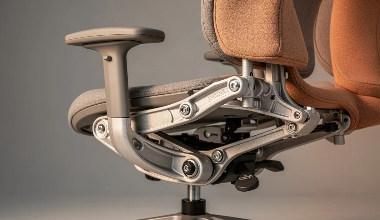
The office chair is rarely evaluated as a piece of heavy machinery, yet it operates under continuous cyclic loads for eight or ten hours each day. Institutional procurement tends to treat seating as a decorative line item, grouping complex articulated assemblies under vague categories of interior finish. This oversight proves expensive. When an occupant sits, their body transfers roughly seventy-four percent of total body weight through the ischial tuberosities and surrounding soft tissue, while the remainder resolves through the floor, armrests, and backrest linkage. If the chair's mechanical interfaces fail to balance these forces dynamically, the occupant unconsciously compensates through postural distortion, generating spinal shear and muscular fatigue.
A rigorous mechanical assessment of task seating requires looking past marketing claims of ergonomic intuition to examine the actual linkages, polymers, and pressurized cylinders that govern movement. Modern task chairs are compound mechanical linkages designed to solve a difficult engineering problem: supporting an articulated biological frame across varying angles of recline without inducing shear along the occupant's spine or restricting femoral circulation. Analyzing these systems demands an appraisal of kinematics, material hysteresis under load, and the structural longevity of primary wear components.
Kinematic Principles of Synchronous Chair Mechanics
The core of modern task seating is the recline mechanism, which controls the spatial relationship between the seat pan and the backrest. Basic tilting chairs rely on a single central pivot, which raises the occupant's knees and lifts their feet off the floor as they recline, compressing the popliteal space behind the knee. More sophisticated assemblies employ synchronous mechanisms, using a four-bar linkage system to coordinate the angular displacement of the seat and backrest at a fixed ratio, typically between 1:2 and 1:2.6. For every two degrees the backrest reclines, the seat pan tilts backward by approximately one degree.
This differential rate preserves the occupant's sightline and ensures their feet remain planted firmly on the floor, preventing the anterior lip of the cushion from pressing into the underside of the thighs. The location of the virtual pivot point determines whether the mechanical motion mirrors human biology. In early synchronous designs, the main pivot was positioned directly above the gas cylinder, several inches forward of the occupant's hip joints. As the backrest reclined, the back cushion slid upward or downward against the occupant's clothing, creating back shear. Contemporary linkages locate the virtual pivot close to the acetabulofemoral joint, allowing the seat and backrest to track the natural articulation of the pelvis with minimal surface displacement.
| Mechanism Type | Mechanical Ratio (Seat:Back) | Primary Pivot Location | Observed Kinematic Limitation |
|---|---|---|---|
| Center-Pivot Tilt | 1:1 fixed | Directly above cylinder | Severe popliteal compression; lifts feet off floor during recline. |
| Knee-Tilt | 1:1 fixed | Anterior edge of seat pan | Eliminates front-edge lift, but alters hip angle rapidly, encouraging slouching. |
| Four-Bar Synchronous | 1:2.1 to 1:2.6 | Virtual pivot near hip joint | Requires precise mechanical calibration to occupant mass for balanced return. |
The resistance within this system is governed by either a steel coil spring or an elastomeric torsion block. Low-cost chairs use a basic compression spring adjusted via a threaded knob that requires up to thirty rotations to move from minimum to maximum preload. Higher-tier assemblies incorporate self-weighing mechanisms. These use a shifting fulcrum or a pantograph linkage that repurposes the occupant's downward gravitational force to set the recline resistance automatically. While convenient in multi-user settings, self-weighing systems often fail to satisfy users at the outer edges of the weight spectrum, who may require manual fine-tuning to achieve neutral equilibrium without holding their core muscles rigid.
Pelvic Rotation and Lumbar Contact Continuity
When an individual moves from an upright standing posture to an unsupported seated position, the pelvis naturally rotates backward by approximately twelve to twenty degrees. This posterior pelvic rotation flattens the natural lordotic curve of the lumbar spine, shifting internal stresses onto the posterior margins of the intervertebral discs and increasing intradiscal pressure within the L4-L5 and L5-S1 segments. The mechanical duty of an ergonomic backrest is not simply to provide a soft pad against the spine, but to arrest this pelvic tilt by stabilizing the sacrum and the posterior superior iliac spine.
Maintaining continuous support across the full range of recline presents an engineering challenge. When an occupant reclines, the angle between the femur and the torso opens up, causing the pelvis to rotate slightly forward again if the lumbar support follows the body correctly. Simple static lumbar pads, typically molded from rigid polypropylene and held in place by friction clips on the backrest frame, fail this kinematic test. They remain anchored to a single point on the backrest, meaning that as the torso pivots, the pad shifts relative to the L1-L5 vertebrae, often ending up wedged against the lower thoracic spine where it pushes the occupant into an unnatural kyphotic posture.
Effective lumbar systems deploy active or articulated tracking. These mechanisms mount the lumbar carriage on a vertical flexure or secondary leaf spring separate from the main perimeter frame. As the occupant reclines, the linkage drives the lower third of the backrest slightly inward, maintaining uniform pressure against the posterior iliac crest without bridging or loss of contact. Where static pads are used, they must feature independent depth and height adjustments with positive detents, ensuring they do not slip downward under the cyclic friction of normal movement.
Tensile Creep in Synthetic Mesh Versus High-Density Foam
The debate between woven synthetic mesh and traditional upholstered polyurethane foam centers on the tradeoff between thermal regulation and load distribution. Elastomeric mesh seating, woven from alternating strands of polyester, nylon, and monofilament elastane, allows continuous air circulation that prevents heat and moisture buildup. Mechanically, however, mesh functions as a catenary suspension system. When a concentrated point load like the ischial tuberosity contacts the mesh, the surface deflects, transferring load tension outwards toward the rigid perimeter frame.
Over extended operational lifespans, polymers subjected to sustained mechanical stress experience tensile creep, an irreversible elongation of the molecular chains. In lower-grade mesh textiles, this shows up after eighteen to twenty-four months as structural sagging. As tension drops, the occupant sinks deeper into the suspension envelope until their thighs or tailbone make contact with the hard structural frame underneath, creating severe localized pressure spikes that impede blood circulation. Premium meshes utilize complex weaves with zoned elasticity, integrating high-modulus fibers across the center and lower-modulus fibers near the periphery to control deflection rates and delay plastic deformation.
Cold-cured molded polyurethane foam operates on a completely different mechanical model: bulk cellular compression. Rather than suspending weight across a perimeter frame, foam absorbs energy through the progressive collapse of microscopic open cells. High-resilience foams formulated with a density between fifty-five and sixty-eight kilograms per cubic meter maintain their structural hysteresis over hundreds of thousands of compression cycles.
- Mesh Suspension: Low thermal mass, minimal shear resistance against clothing, highly vulnerable to perimeter frame interference if tensile elasticity falls by more than eight percent.
- Polyurethane Foam: Predictable dampening, distributes high-load concentrations across a wider surface area, but prone to heat retention and eventual chemical breakdown if exposed to high ambient humidity.
- Hybrid Assemblies: Cold-cure foam base with a tensioned textile overlay, balancing local pressure distribution with surface airflow, though at the cost of mechanical complexity and weight.
Foam cushions molded with varying internal densities, softer beneath the ischial bones and firmer around the lateral edges, provide superior long-term positional stability compared to pure mesh, which tends to pull the occupant into the lowest point of its sag pocket.
Dimensional Adjustment Thresholds for Diverse User Groups
Anthropometric distribution curves make it impossible for a task chair with fixed geometry to accommodate a standard workforce. Guidelines such as ANSI/BIFMA X5.1 and EN 1335 dictate that task seating should fit populations spanning from the fifth percentile female to the ninety-fifth percentile male. Satisfying this demographic envelope requires distinct adjustment ranges across four primary axes: seat height, seat depth, armrest position, and backrest inclination.
Seat depth adjustment represents a critical boundary condition. If a seat pan is too deep, the leading edge strikes the back of the occupant's calves, forcing them to sit forward and disengage from the lumbar support. If it is too shallow, the contact surface drops below acceptable thresholds, concentrating weight onto a small strip of the thighs. A minimum horizontal adjustment stroke of sixty millimeters, delivered via a sliding plate with locking detents spaced no more than ten millimeters apart, is necessary to bridge this anatomical variance.
Armrest mechanics require comparable latitude. Fixed armrests frequently collide with worksurface edges, preventing the occupant from pulling the chair in close enough to reach input devices without hunching. To prevent this, armrest carriages must incorporate three degrees of freedom: height travel of at least eighty millimeters, lateral width adjustment of fifty millimeters, and depth adjustment of forty millimeters. The internal locking detents must resist a vertical downward force of at least four hundred Newtons without slipping, ensuring the user can lean on the arm pads when standing up without causing the mechanism to collapse.
Maintenance and Replacement Cycles for Pneumatic Cylinders
The pneumatic cylinder, or gas lift, serves as the main structural column of the chair, combining vertical dampening with continuous height adjustment. These components operate as closed nitrogen gas springs, pressurized internally between forty and seventy bar. The assembly relies on a hardened steel piston rod moving within an outer casing, sealed by an arrangement of nitrile rubber O-rings, polyurethane scrapers, and internal valve pins.
Pneumatic cylinders are standardized under DIN 4550 into performance classes based on wall thickness and impact resistance:
| Class Rating | Wall Thickness | Rated Working Load | Typical Duty Cycle |
|---|---|---|---|
| Class 2 | 1.5 mm | Up to 100 kg | Light residential or sporadic commercial use. |
| Class 3 | 2.0 mm | Up to 135 kg | Standard institutional office environments (single shift). |
| Class 4 | 2.5 mm | Up to 180 kg | Demanding commercial, control room, or continuous shift facilities. |
The primary failure mode of a gas lift is gradual pressure loss caused by seal wear. Micro-scratches on the surface of the chrome-plated piston rod, often introduced by ambient grit or sideways deflection forces from an occupant shifting their weight unevenly, allow nitrogen to escape past the seals. This shows up as a creeping drop in seat height over several hours, or a complete drop to the bottom stop under initial impact. When replacement becomes necessary, the following procedure ensures safe extraction from the tapered press-fit joint:
- Invert the chair and rest the upper chassis securely on an elevated work bench, leaving the five-star base suspended freely.
- Apply a penetrating fluid around the tapered interface where the gas cylinder enters the bottom of the mechanism housing and where it joins the central hub of the base. Allow ten minutes for capillary action to break surface oxidation.
- Using an aluminum drift or a heavy dead-blow hammer, strike the central casting of the star base sharply adjacent to the cylinder receiver to break the lower Morse-style taper fit. Avoid striking the cylinder pin directly.
- Clamp a heavy-duty pipe wrench around the upper section of the exposed cylinder casing, close to the mechanism housing. Rotate the wrench sixty degrees with a sudden, firm impulse to break the friction weld of the upper taper joint.
- Clean the tapered receptors in the mechanism and base with a degreaser before pressing the replacement Class 4 cylinder into place by hand. The tapers are designed to lock permanently through the occupant's downward weight upon initial seating.
Common Mistakes
Facilities managers and individual users regularly make fundamental errors when specifying, using, and maintaining mechanical seating:
- Locking the recline mechanism permanently: Restricting the backrest to a rigid ninety-degree vertical position increases lumbar disc pressure by preventing the periodic load shifting that keeps spinal tissues hydrated. Dynamic movement should be encouraged by setting the tension spring correctly rather than locking the backrest upright.
- Over-tightening mechanical tension controls: Cranking tilt tension knobs past their designed travel limits can bind internal lead screws or strip fine plastic threads, preventing proper auto-balancing.
- Lubricating piston rods with petroleum oils: Spraying penetrating oils or grease onto the exposed chrome shaft of a gas cylinder attracts dust and degrades the internal polyurethane wiper seal, accelerating gas leaks. Piston shafts should only be wiped clean with a dry, lint-free cloth.
- Ignoring base diameter in high-travel environments: Pairing a narrow five-star base (under six hundred millimeters in diameter) with a long-stroke gas cylinder moves the center of gravity outward when reclined, creating a tipping risk that fails stability standards.
Practical Next Steps
Evaluating an existing fleet of task seating requires a structured mechanical assessment rather than subjective comfort surveys. Begin by conducting a physical inspection of every chair in service for longer than thirty-six months. Check the gas cylinders for vertical drift under a test load, inspect cast aluminum mechanism housings for hairline fatigue cracks near pivot pins, and examine the underside of mesh seat pans for fiber fraying or tension loss.
When drafting technical specifications for new procurement, require suppliers to submit test certificates verifying compliance with ANSI/BIFMA X5.1 or EN 1335, and explicitly mandate Class 4 gas cylinders with DIN 4550 ratings. Avoid single-piece shell designs that lack independent seat depth adjustment if the user group includes varying body sizes. Finally, where dynamic task seating is intended to manage chronic musculoskeletal discomfort for specific staff members, engage a certified professional ergonomist or an occupational health specialist rather than relying on standard furniture dealership recommendations.