 Architrave Journal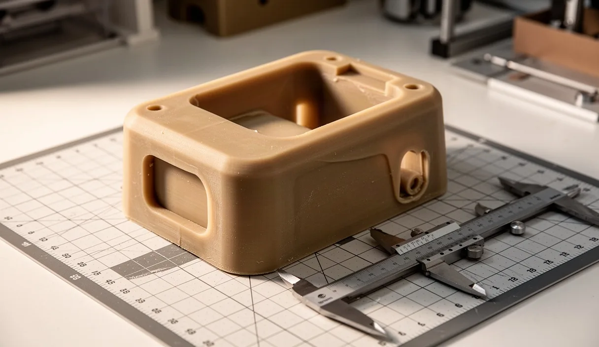
The selection of an enclosure material for heavy analytical instruments, robotics enclosures, and low-run industrial plant equipment typically forces an uneasy compromise. Sheet metal fabrication offers low barrier to entry for prototype runs, yet it imposes severe geometric penalties whenever compound curvatures, integrated acoustic dampening, or weight reduction become engineering imperatives. Conversely, standard thermoplastic injection molding delivers exquisite volumetric efficiency and part integration, yet its upfront tooling costs presuppose production volumes that specialized industrial hardware rarely achieves over an entire commercial lifespan.
Reaction injection molding (RIM) utilizing cast thermoset polyurethane occupies the territory between these extremes. By impinging low-viscosity liquid components at comparatively moderate hydraulic pressures, the process frees the tool designer from the clamping tonnage and thick-to-thin section ratios that dictate thermoplastic part design. The resulting structural foam or solid elastomeric matrix yields an exterior casing capable of absorbing mechanical abuse and housing complex internal architecture. However, deploying polyurethane successfully requires an unsparing understanding of its polymerization kinetics, thermal shrinkage, and unique structural mechanics.
Chemical Dynamics of Two-Component Reaction Injection Molding
The manufacturing of polyurethane industrial shells rests on the rapid impingement mixing of two liquid streams: a formulated polyol blend and a polymeric isocyanate, typically diphenylmethane diisocyanate (MDI). The polyol stream contains long-chain polyether or polyester backbones, crosslinkers such as diethanolamine, chain extenders like 1,4-butanediol, catalysts (often organotin compounds combined with tertiary amines), and chemical or physical blowing agents. When brought together under pressures ranging between 135 and 205 bar within a high-pressure mixhead, the collision breaks the liquids into micro-droplets, initiating an exothermic polyaddition reaction without requiring external heating.
Upon discharge into the mold cavity, the material transitions through distinct rheological states. Unlike molten thermoplastics that cool from the outside inward against cold metal walls, the polyurethane mixture flows like heavy oil, wets the mold details under low internal cavity pressures (typically between 3 and 10 bar), and subsequently gels as the urethane and urea linkages form an interlocking polymer network. When chemical blowing agents (such as water reacting with isocyanate to liberate carbon dioxide) are present, the expanding gas drives the forming polymer outward against the mold surface, establishing a natural density gradient.
This kinetic sequence produces what polymer physicists call an integral skin structure. The cooling effect of the mold face suppresses cell expansion in the outermost layer, yielding a solid, non-porous surface skin measuring roughly 1.5 to 2.5 millimeters in thickness. Toward the geometric core of the wall, where reaction heat dissipates more slowly, the gas bubbles expand into a microcellular core with cell diameters between 50 and 150 microns. The final component therefore functions as a continuous sandwich beam, maximizing the section modulus and moment of inertia while decreasing gross mass by 28 to 36 percent relative to solid cast polyurethane resin.
Tooling Investment Analysis Across Moderate Batch Sizes
Tooling economics fundamentally dictate why polyurethane RIM finds its primary application in runs of 250 to 3,500 units per year. Because cavity pressures remain under 10 bar, the mold construction does not demand forged P20 or H13 tool steel, nor does it require massive hydraulic clamping platens capable of countering thousands of kilonewtons. Instead, tools are routinely machined from forged 6061-T6 or 7075 aluminum plate, or cast from aluminum patterns for exceptionally large geometries with sweeping, organic radii.
| Parameter | Fabricated 5052 Sheet Aluminum | RIM Cast Polyurethane (Aluminum Tool) | Injection Molded Polycarbonate/ABS (P20 Steel) |
|---|---|---|---|
| Upfront Tooling Capital | $3,500 - $7,000 | $22,000 - $48,000 | $115,000 - $190,000 |
| Piece-Part Production Cost | $165 - $240 | $72 - $115 | $24 - $38 |
| Economic Break-Even Volume | 1 to 180 units | 181 to 4,200 units | 4,201 units and upward |
| Geometric Freedom Index | Constrained (linear bends) | Extensive (variable walls, ribs) | High (restricted by wall uniformity) |
| Lead Time to First Samples | 2 to 4 weeks | 7 to 10 weeks | 18 to 26 weeks |
Machined aluminum tooling maintains dimensional tolerances within plus or minus 0.08 millimeters across a 600-millimeter span, which is more than adequate for high-end diagnostic shells and machine cowlings. Furthermore, aluminum exhibits superior thermal conductivity compared to steel, dissipating the exothermic reaction heat uniformly and shortening cycle times to roughly 4 to 8 minutes per demold cycle. For production volumes lower than 300 parts across a product lifecycle, structural silicone or epoxy composite tooling can even be considered, though composite tools exhibit poor heat dissipation and degrade after approximately 150 to 250 cycles due to exothermic thermal spiking.
When analyzing amortization, the total cost equation must account for downstream operations. While a folded sheet metal enclosure avoids initial tooling expenses, it demands substantial manual labor for welding, grind-out of seams, secondary bracket installation, and powder coat prep. Polyurethane tooling consolidates six to twelve discrete structural brackets, bezel attachments, and acoustic baffles into a single shot, lowering assembly floor time from hours to minutes.
Rib Design, Bosses, and Wall Thickness Tolerances
The rules governing rib and boss geometry in reaction injection molded parts diverge sharply from the orthodox guidelines associated with injection molding. In standard thermoplastics, rib thickness must not exceed 50 to 60 percent of the adjacent nominal wall, lest differential cooling shrinkage pull the surface inward and create unsightly sink marks visible on class-A surfaces. Because polyurethane RIM experiences volumetric change primarily during the liquid-to-solid transition while simultaneously expanding via microcellular foaming, the material is considerably less prone to sink defects.
Consequently, structural ribs in polyurethane shells can safely measure up to 80 or even 100 percent of the adjacent wall thickness, provided proper draft angles are honored. A nominal wall of 6.0 millimeters can support a 5.0-millimeter-thick rib without generating noticeable aesthetic witness marks on the reverse cosmetic face. This characteristic permits the engineering of exceptionally stiff structural walls without the need to scatter dozens of spindly, thin-bladed ribs across the interior surface. Incorporating a draft angle of 1.5 to 3.0 degrees remains mandatory along vertical rib surfaces to allow clean release from aluminum tooling without scuffing the cured integral skin.
Fastener bosses require equal geometric discipline. To avoid stress concentrations and support dynamic pull-out loads, designers should avoid freestanding bosses isolated in open spans. Best practice ties the boss directly into the adjacent sidewall using structural gussets angled at 45 degrees:
- Outer Diameter: The outside diameter of the boss should measure roughly 2.0 to 2.4 times the diameter of the thread insert.
- Cored Depths: Core pins must extend to within 2.0 millimeters of the nominal wall face to avoid heavy, uncured resin pools that alter localized density.
- Thread Inserts: Brass or stainless steel threaded inserts can be pressed in ultrasonically, installed cold via expansion knurls, or molded directly in place during the pour cycle. Molded-in inserts offer the highest pull-out resistance, frequently exceeding 4,800 Newtons in a 6.0-millimeter boss, though they increase cycle time as the press operator must seat the hardware manually prior to mold closure.
- Wall Thickness Transitions: Transitions between varying wall sections (such as a drop from an 8.0-millimeter mounting perimeter to a 4.5-millimeter acoustic canopy) should be blended via gradual tapers over a distance of at least three times the differential thickness. Step transitions disrupt chemical flow paths and generate turbulence that traps air cells against the tool surface.
Impact Resistance Comparison: Polyurethane Versus Sheet Aluminum
Selecting between cast polyurethane and 5052-H32 sheet aluminum for industrial machinery covers frequently boils down to how each material dissipates dynamic impact energy. Aluminum behaves in a classic elastic-plastic manner. Upon receiving an impact from a tool drop, a swinging hoist hook, or transit shock, aluminum absorbs energy through elastic flexure until its yield point (roughly 195 MPa for 5052-H32) is exceeded. Once past this threshold, the metal deforms plastically, leaving permanent indentations, creased radii, and cracked coatings that demand panel replacement or intensive bodywork.
In contrast, structural polyurethane RIM systems (such as high-modulus dicyclopentadiene-modified or polyurea-hybrid formulations) absorb kinetic energy through viscoelastic damping. When subjected to impact, the material exhibits high instantaneous stiffness followed by strain-rate dependent molecular relaxation. The solid outer skin sheds localized compressive stresses, while the closed-cell elastomeric core compresses elastoplastically, distributing the load over an area three to four times wider than the initial point of impact. In testing regimes modeled after ASTM D5420 (Gardner Impact), a 6.0-millimeter solid skin polyurethane panel routinely absorbs impacts exceeding 45 Joules without catastrophic puncture or permanent surface deformation, snapping back to its original geometric profile once the stress dissipates.
Environmental resonance represents an additional, often overlooked operational metric. Sheet aluminum displays a high acoustic Q-factor, meaning it rings like a bell when excited by internal motors, pumps, or gear assemblies, necessitating the application of secondary, adhesive-backed bitumen deadening pads. Cast polyurethane possesses inherently high loss factors, typically exhibiting an internal mechanical damping coefficient (tan delta) between 0.04 and 0.09 at room temperature. This internal loss converts operational acoustic energy into microscopic amounts of frictional heat within the polymer backbone, quieting the perceived sound pressure of industrial machinery without added secondary materials.
Finishing Protocols and In-Mold Coating Technology
Polyurethane parts discharged from bare tooling are not ready for cosmetic deployment. The process demands external mold release agents, typically paste waxes or synthetic polymeric liquids containing fluoropolymers or silicones, to prevent the intensely adhesive urethane chemistry from bonding permanently to the aluminum tool. Residual release agents must be thoroughly addressed before any paint system will adhere to the part.
The standard post-mold finishing sequence follows four distinct operational checkpoints:
- Solvent Degreasing and Mechanical Scuffing: Parts are washed using aromatic hydrocarbon or waterborne alkaline cleaning formulations to strip surface release waxes. Following degreasing, the Class-A cosmetic surfaces are manually or robotically abraded with non-woven abrasive pads (typically 320 to 400 grit) to remove micro-porosity and break the continuous gloss of the integral skin, providing a mechanical key for primers.
- De-gassing Bake Cycle: Polyurethanes can retain trace amounts of blowing agents and moisture within their microcellular cores. Placing parts in a convection oven at 65 to 80 degrees Celsius for roughly 90 minutes drives out residual volatile compounds, mitigating the risk of micro-bubbling or pinholing during subsequent paint curing cycles.
- Conductive Priming: Because polyurethane is an electrical insulator, applying electrostatic coatings requires a preparatory conductive primer layer. This coat, measuring 20 to 30 microns, ensures wrap-around paint coverage across recessed gasket channels and undercuts.
- Topcoat Application: High-solids, two-component aliphatic polyurethane paints are spray-applied to build a 35 to 50-micron barrier layer. Aliphatic chemistries provide vital resistance to ultraviolet degradation, organic solvents, and caustic chemical washdowns common in medical and food processing environments.
An increasingly attractive alternative to secondary painting is In-Mold Coating (IMC). In this protocol, an automated spray head applies a specialized, fast-reacting, two-component aliphatic coating directly onto the hot aluminum mold surfaces prior to the injection of the polyurethane core. The mold coat support partially to a tacky, high-density film over 45 to 90 seconds. When the liquid MDI-polyol mixture is shot into the tool, the expanding substrate chemically reacts across the interface, crosslinking with the coating rather than simply creating a mechanical bond. In-mold coating eliminates post-mold cleaning, primer applications, and paint emissions while yielding a composite shell with abrasion resistance superior to standard post-applied coatings.
Common Mistakes in Polyurethane Enclosure Design
Engineering teams transitioning from sheet metal or conventional thermoplastics into reaction injection molding frequently stumble over several subtle material idiosyncrasies. The most pervasive error is ignoring anisotropic thermal expansion. Cast polyurethane displays a coefficient of linear thermal expansion (CLTE) varying between 65 x 10^-6 and 110 x 10^-6 m/m/K, roughly four to five times that of standard carbon steel or structural aluminum subframes. When long polyurethane shells (exceeding 1,000 millimeters) are rigidly fastened to an internal aluminum or steel skeleton without slotted clearance holes or elastomeric grommets, ambient temperature swings will cause the shell to buckle or crack across its mounting perimeters.
Another persistent failure occurs during the specification of fire retardancy and environmental compliance. Polyurethane chemistry is inherently organic, requiring tailored additive packages to pass flammability certifications like UL 94 V-0 or EN 45545. Designers frequently assume all rigid RIM polyurethanes meet self-extinguishing criteria by default; un-modified systems will burn persistently and produce dense smoke. Halogenated or phosphorus-based flame retardants must be deliberately specified during raw resin formulation, which marginally increases viscosity, lowers unnotched Izod impact resistance by 12 to 18 percent, and requires tighter processing windows in the metering equipment.
Finally, molders occasionally attempt to vent tools incorrectly. Because reaction injection molding occurs at lower pressures than injection molding, venting must occur precisely where the rising liquid front terminates. Failing to locate tool parting lines and porous stainless vent plugs at the absolute geometric high points of the mold cavity traps pocketed gas. Trapped gas resists displacement, yielding uncompacted skin, brittle margins, and unsightly voids that cannot be remedied with cosmetic body filler.
Implementation Framework
Before committing capital to aluminum tooling, design teams should follow a structured physical verification sequence. Fabricating a functional prototype via large-format stereolithography (SLA) or selective laser sintering (SLS) is essential, but designers must remember that printed specimens lack the density gradient and viscoelastic dampening of an integral skin polyurethane part. 3D prints serve strictly to evaluate clearance relative to internal mechanical sweeps, cable harness pathways, and thermal exhaust ducting.
Once geometric package dimensions are frozen, engage directly with a specialized RIM formulator and a moldmaker who works routinely with aluminum block cavity construction. Mechanical and chemical engineers should audit the proposed formulation, verifying that flexural modulus, heat deflection temperature (HDT at 1.82 MPa), and long-term chemical exposure limits match the real-world operating environment. If flammability or marine certifications are legally binding for the end-use device, certification bodies must be brought in early to inspect plaque specimens cast directly from trial polyol-isocyanate lots before manufacturing the primary aluminum production tooling.