 Architrave Journal
The contemporary preference for expansive, uninterrupted domestic interiors has outpaced the acoustic conventions that once governed residential design. When perimeter walls, compartmentalized vestibules, and cellular floor layouts are erased in favor of continuous sightlines, the physical boundaries that traditionally contained, absorbed, and diffused airborne energy disappear. The outcome is familiar to anyone who has occupied a modern open plan with stone floors and floor-to-ceiling glazing: conversational sound bleeds into culinary tasks, the clatter of dishware carries across sixty linear feet of living space, and speech intelligibility degrades into a low, fatiguing rumble.
Remediating these environments requires an architectural approach that rejects both the aesthetic surrender of glued-on foam panels and the acoustic fatalism that assumes open plans must remain clamorous. By treating the open floor plate not as a singular void, but as an assembly of distinct micro-environments or acoustic zones, architects can establish localized clarity without reintroducing rigid load-bearing partitions. This approach demands a clear grasp of wave decay over unconfined distances, careful calibration of finish weights, and the integration of joinery and ceiling planes as functional sound attenuators.
Acoustic Decay in Large Unpartitioned Spaces
In a small, enclosed room, sound energy quickly encounters boundaries, establishing a reverberant field governed largely by diffuse reflections. In an open domestic plan spanning one hundred square meters or more, the behavior shifts toward semi-free field conditions over short distances, complicated by erratic reflections off distant, parallel boundaries. High-frequency content, such as consonant sounds and culinary activity between two kilohertz and four kilohertz, dissipates naturally over distance via atmospheric absorption and inverse-square dispersion. However, low- and mid-frequency energy generated by footfall, mechanical systems, and low vocal registers travels through an open room with minimal attenuation.
This dynamic creates a skewed acoustic environment where the crisp, directional cues of human speech are lost, while the muddy fundamentals between two hundred and fifty and five hundred hertz linger. The architectural consequence is the Lombard effect: occupants unconsciously raise their vocal projection to overcome ambient reverberation, which in turn raises the overall floor noise and forces others to speak louder still. Without physical intervention, an open living, dining, and kitchen pavilion becomes unusable for simultaneous activities.
Controlling this decay without active vitality full-height walls depends on manipulating two physical factors: the critical distance of sound sources and the specular reflection characteristics of the floor and ceiling. The critical distance marks the point where the direct sound pressure level equals the reverberant sound pressure level. In a poorly damped open room, this distance can be as short as 1.2 meters from the speaker. By using targeted absorption and diffraction to extend the critical distance to 2.8 or 3.2 meters, occupants can converse at normal speech volumes without their voices dominating adjacent zones.
Calculating Surface Mass and Reverberation Metrics
Acoustic planning must be backed by empirical calculation rather than subjective material selection. The standard calculation for reverberation time is the Sabine formula, which correlates internal room volume with total equivalent absorption area. For open residential areas, the target reverberation time (RT60) should generally sit between 0.55 and 0.70 seconds across the speech frequencies. Measurements exceeding 0.85 seconds inevitably produce the sensory fatigue common to concrete-and-glass domestic projects.
The calculation requires tabulating the surface area of every material assembly multiplied by its respective sound absorption coefficient (alpha) across the standard octave bands: one hundred twenty-five, two hundred fifty, five hundred, one thousand, two thousand, and four thousand hertz. When working with typical domestic finishes, the disparity in absorption is stark. Polished poured concrete and large-format porcelain tile yield an alpha value of roughly 0.02 at five hundred hertz, reflecting 98% of incident sound energy. Heavy timber flooring over an acoustic underlayment may yield an alpha of 0.08, while micro-perforated timber paneling with a mineral wool cavity can deliver 0.74 across the same frequency range.
| Material Assembly | Surface Mass (kg/m²) | NRC (Average) | Primary Acoustic Function |
|---|---|---|---|
| Poured concrete slab, sealed (150 mm) | 345 | 0.03 | Specular reflection; structural transmission |
| Standard gypsum board on steel studs (13 mm) | 9.8 | 0.07 | Low-frequency membrane resonance |
| Dual gypsum board with damping compound (26 mm) | 21.5 | 0.12 | Mid-to-low frequency isolation |
| Slotted timber panel with 50 mm acoustic wool (30 kg/m³) | 14.2 | 0.72 | Mid-range absorption and attenuation |
| Micro-perforated veneer over porous substrate (19 mm) | 11.8 | 0.68 | High-speech intelligibility balance |
Surface mass also plays a subtle role in architectural acoustics. Lightweight surfaces, such as standard single-layer gypsum wallboard on lightweight metal track, act as diaphragmatic absorbers that flex in response to low-frequency energy. While this helps absorb some low bass, it transmits sound directly into adjacent structural cavities if uninsulated. Increasing surface mass to at least twenty kilograms per square meter using staggered layers of dense board suppresses boundary flanking, ensuring that sound remains contained within the zone where it is produced.
Strategic Placement of Free-Standing Joinery Partitions
When architectural program briefs rule out permanent full-height partitions, free-standing millwork provides an effective alternative for spatial and acoustic subdivision. A credenza, library wall, or kitchen larder that stops 400 to 600 millimeters short of the ceiling maintains spatial continuity while acting as an acoustic screen. For an acoustic barrier to be effective, sound waves must not easily diffract over the top, meaning the barrier height must exceed the standing ear height of an adult (at least 1.8 meters) and possess adequate internal mass.
A hollow millwork partition constructed of sixteen-millimeter particleboard serves as an acoustic drum, amplifying mechanical noise and vocal chatter through internal cavity resonance. To perform as a true sound break, joinery must be detailed with internal damping layers:
- Line internal carcass voids with dense stone mineral wool batts rated at no less than forty-five kilograms per cubic meter.
- Incorporate a staggered stud or decoupled double-carcass construction so that drawer closures and cabinet doors on one face do not telegraph vibration through to the opposite face.
- Ensure that the partition forms an airtight seal against the finished floor using a closed-cell neoprene gasket compressed under a concealed structural plinth.
- Face the noise-generating zone, such as an informal dining table or kitchen prep island, with micro-perforated or slatted surfaces backed by black acoustic tissue, turning the joinery face into a distributed absorber.
The geometric alignment of these free-standing units matters just as much as their assembly. Aligning joinery pieces directly opposite reflective glass walls creates flutter echoes, where high-frequency sounds ping back and forth between two parallel faces. Angling the joinery face by as little as four to six degrees from the structural axis breaks the flutter pattern, scattering early reflections upward toward an absorptive ceiling plane rather than horizontal into the adjoining lounge.
Ceiling Plane Modulation and Baffle Integration
Floors in open domestic spaces are subject to heavy wear, spill hazards, and aesthetic requirements that usually preclude dense wall-to-wall carpeting. The ceiling therefore represents the single largest unobstructed surface for acoustic intervention. A monolithic, smooth plasterboard ceiling stretching across an open plan functions as an acoustic mirror, collecting noise from the kitchen and broadcasting it down into the reading area or lounge. Modulating this plane through variations in height, coffering, and integrated absorptive baffles is essential to domestic zoning.
Dropping the ceiling plane over a dining or conversation nook from 3.2 meters down to 2.4 meters alters the acoustic character immediately. This compression reduces the local room volume, limits early reflection delay times, and produces an intimate auditory field. If this dropped soffit is detailed with an acoustic plaster system or a suspended timber-slat system over fifty millimeters of acoustic fleece, it functions as a localized sound sink, trapping noise before it can propagate across the wider floor plate.
Where flat finishes are preferred, high-density mineral wool boards finished with seamless, micro-porous acoustic plaster allow the ceiling to look identical to traditional painted drywall while achieving an NRC rating of 0.80 or higher. For larger spaces with a more industrial architectural language, linear timber baffles or high-density polyester fiber fins suspended on concealed suspension wires introduce valuable acoustic friction. Spacing the fins at intervals equal to their depth (for instance, one hundred millimeter deep fins spaced one hundred millimeters on center) maximizes wave disruption across speech frequencies, preventing sound from skimming unobstructed across the upper horizontal datum of the space.
Field Errors in Residential Acoustic Detail Execution
The performance of an acoustic assembly often fails on site rather than in design documents. Small mechanical and framing compromises can severely degrade a carefully modeled acoustic zone. Site supervision must focus on continuous seals and decoupling.
One prevalent field error is the incomplete acoustic sealing of joinery perimeters. An air gap of only two millimeters along the base of an otherwise dense custom credenza can leak up to 30% of airborne acoustic energy directly across the floor line. Trades often rely on standard plastic shims and finish trims without packing the void. All floor and wall interfaces beneath acoustic millwork must be packed with non-hardening acoustic mastic or pre-compressed expanding foam tapes before finish trim installation.
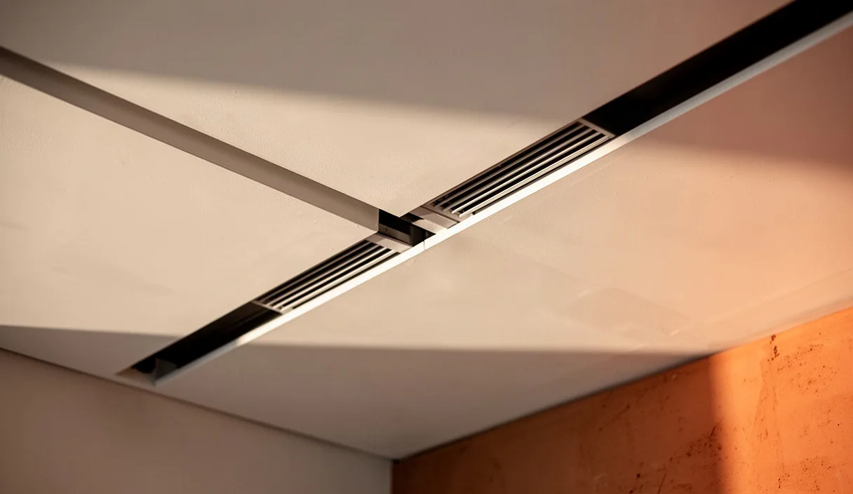
A second common mistake occurs during the installation of recessed services within acoustic ceilings. An architect may specify a high-performance perforated acoustic gypsum ceiling, only to have the electrical contractor install dozens of unsealed, unlined recessed downlight cans and continuous linear diffusers. Each penetration pierces the acoustic membrane, venting acoustic energy straight into the plenum, where it resonates against structural slabs and re-radiates into quiet zones. All ceiling penetrations must be enclosed in prefabricated acoustic backing boxes made from fire-rated acoustic boards or heavy-density mineral wool enclosures.
Common Mistakes
Acoustic zoning failures typically stem from predictable design oversights during the early spatial planning phase. Identifying these common missteps helps preserve project budgets and acoustic performance:
- Specifying sound absorption only in the vocal frequencies while ignoring the low-frequency drone produced by kitchen refrigeration compressors and continuous ventilation runs.
- Placing heavy, reflective furniture elements, such as solid marble dining tables or glazed display cabinets, directly in the direct-line reflection path between the kitchen island and the television lounge.
- Assuming that rugs and decorative window drapery provide sufficient acoustic damping; standard ten-millimeter decorative rugs lack the density and underlay required to absorb energy below one thousand hertz.
- Treating only vertical surfaces while leaving two parallel, hard planes, such as polished concrete floors and flush plasterboard ceilings, completely exposed to one another.
- Over-damping a single zone to an RT60 below 0.35 seconds, which feels unnaturally dead and oppressive to occupants, while leaving the adjacent zone completely untreated.
Implementing an Acoustic Strategy
An effective acoustic zoning scheme begins during schematic design, before structural drawings and mechanical duct pathways are finalized. Architectural teams should approach the layout through systematic steps that integrate sound management directly into the space planning process.
First, draft an acoustic mapping overlay across the schematic floor plan. Categorize programmatic areas into clear acoustic categories: sound-generative (kitchens, play spaces, media centers), intermediate (dining rooms, casual seating), and noise-sensitive (home offices, reading corners, library nooks). Identify the direct sound paths connecting these zones, paying special attention to uninterrupted horizontal sightlines.
Next, model the equivalent absorption area of the proposed shell using the Sabine formula to establish a baseline reverberation estimate across the standard speech octaves. If the calculated RT60 exceeds 0.65 seconds, allocate architectural surface treatments to absorb energy at the primary reflection points. Prioritize the ceiling plane above noise-generative zones and the vertical faces of free-standing joinery.
Finally, incorporate precise acoustic details into the construction drawing set. Detail perimeter mastic joints, specify acoustic underlayments with specific laboratory-verified dynamic stiffness ratings, and mandate acoustic backing hoods for all downlights and ceiling speakers. For complex open spaces where large expanses of structural glass intersect with exposed concrete structures, consult an acoustic engineer early in the technical design phase to run ray-tracing simulations and calibrate composite surface treatments.