 Architrave Journal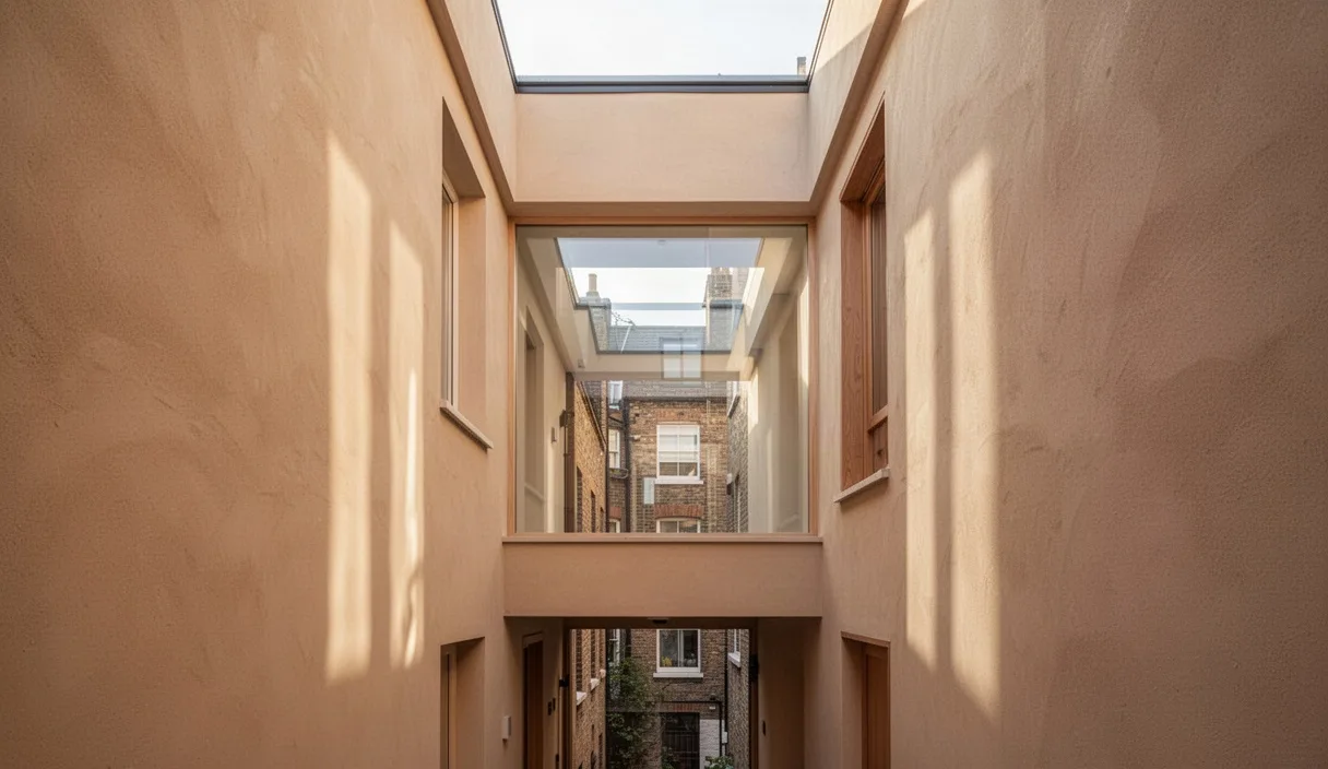
The urban rowhouse presents one of the most stubborn geometric puzzles in residential architecture. Characterized by narrow frontages that typically span between 4.2 and 6.0 meters, coupled with structural depths frequently exceeding 15 to 22 meters, these party-wall envelopes rely entirely on their terminal facades for natural ventilation and daylighting. As urban centers densify and adjacent structures cast deeper site shadows, interior cores inevitably languish in semi-permanent gloom, compelling occupants to burn artificial lighting at midday merely to navigate a ground-floor kitchen or interior stair hall.
Remediating this deficit requires moving past approximate architectural heuristics. Relying on rule-of-thumb window-to-floor area ratios invariably fails within constricted urban plots because it assumes an unoccluded sky dome. In an urban rowhouse context, daylight penetration is dictated not only by the glass dimension, but by the exterior obstruction angle of neighboring facades, the light well wall reflectance, the light-to-solar-gain ratio of performance glazing, and the geometry of cross-sectional light shafts. Precision calculations, rather than generous assumptions, are required to secure usable natural light within the innermost third of the building footprint.
Formulas for Daylight Factor in Constrained Urban Sites
The Daylight Factor method remains the standard baseline for evaluating diffuse sky contribution in temperate climates. Defined under the Commission Internationale de l'Eclairage overcast sky conditions, the Daylight Factor represents the ratio of internal illuminance at a specific point on the working plane to the simultaneous outdoor illuminance available on an unobstructed horizontal surface, expressed as a percentage. The standard formulation breaks the internal illumination into three distinct components:
Daylight Factor = SC + ERC + IRC
The Sky Component denotes the light received directly from the visible portion of the sky. In a rowhouse bordered by buildings of equal or greater height across an eight-meter street, the vertical obstruction angle often approaches 42 to 58 degrees. This severe cutoff sharply constricts the Sky Component across the lower levels, relegating ground-floor rooms to marginal direct sky exposure. The Externally Reflected Component accounts for the light bouncing off opposing facades, calculated by multiplying the luminance of the opposing wall by its visible solid angle from the reference point. The Internally Reflected Component quantifies the light scattered by room surfaces, which Hopkinson, Longmore, and Petherbridge formalized through the split-flux equation:
IRC = (T * W / A * (1 - R)) * (C * R_floor + R_ceiling)
In this equation, T represents the diffuse visual transmittance of the glazing unit (incorporating a maintenance depreciation factor of 0.82 to 0.90 for atmospheric dirt), W is the net glazed area, A is the total internal room surface area, and R is the area-weighted average reflectance of all interior finishes. The scalar C accounts for sky obstruction, shifting between 39 and 18 as the external skyline obstruction angle climbs from zero to 60 degrees. On a constrained plot where the Sky Component drops below 0.4 percent at three meters inward from the glass, the Internally Reflected Component must supply the remaining illumination. Achieving an interior Daylight Factor of 1.8 percent requires ceiling reflectances of at least 0.82 and wall reflectances hovering near 0.65, values typical of matte white and very pale neutral paints.
Sizing Central Light Shafts for Deep Residential Plans
When floorplate depth exceeds 2.5 times the clear ceiling height, perimeter fenestration cannot cast adequate light into the middle zone. Inserting an internal light shaft or courtyard becomes unavoidable. The functional performance of a vertical light well depends on its Well Cavity Ratio, which models the vertical shaft as an optical cavity with cumulative surface absorption.
The Well Cavity Ratio is determined by the equation:
WCR = 2.5 * H * (L + W) / (L * W)
Here, H is the total height of the shaft from the ceiling plane of the target room to the roof coping, while L and W represent the length and width of the light well cross-section. As the Well Cavity Ratio climbs above 4.5, light attenuation accelerates nonlinearly. In a typical three-story rowhouse with a shaft height of 9.4 meters, a shaft measuring 1.8 by 2.4 meters yields a Well Cavity Ratio of 6.35, resulting in severe light extinction at the ground floor unless wall reflectance is maintained above 0.78.
| Shaft Dimensions (m) | Well Cavity Ratio (3 Storeys) | Well Efficiency (0.50 Wall Reflectance) | Well Efficiency (0.80 Wall Reflectance) |
|---|---|---|---|
| 1.5 x 1.5 | 8.35 | 0.08 | 0.23 |
| 2.0 x 2.5 | 5.28 | 0.17 | 0.41 |
| 3.0 x 3.0 | 4.17 | 0.24 | 0.52 |
| 3.0 x 4.5 | 3.26 | 0.33 | 0.64 |
As the table demonstrates, relying on standard painted masonry with a typical reflectance of 0.50 within a tight shaft (1.5 by 1.5 meters) reduces light transmission to 0.08 of incoming roof light, rendering the bottom level effectively dark. Upgrading the internal shaft skin to glazed ceramic panels or back-painted glass panels with a verified reflectance of 0.80 nearly triples performance. Designers working on sites under five meters wide should consider a single asymmetrically placed courtyard rather than a centered well, prioritizing a minimum cross-sectional dimension of 2.2 meters to ensure usable ground-level daylighting.
Clerestory Geometry and Direct Glare Mitigation
Top-floor additions, rear extensions, and double-height core volumes offer the opportunity to employ clerestory windows. When designing clerestories on narrow sites, direct south-facing glazing without angular cutoffs creates high local contrast ratios, resulting in severe glare and unwanted solar heat gain. To maintain visual comfort, the maximum luminance contrast between a fenestration aperture and the immediately surrounding wall plane must not exceed a ratio of 10 to 1.
Mitigating this contrast requires manipulating the reveal geometry. By angling window jambs, sills, and lintels at 35 to 45 degrees relative to the glazing plane, the architect introduces a transitional luminance surface. Light grazing across these angled reveals bridges the steep drop between outdoor sky brightness, which may exceed 6,500 candelas per square meter, and interior wall surfaces, which often sit below 180 candelas per square meter under overcast skies.
The optimum clerestory sill height can be derived by establishing the occupants' horizontal sight lines and shielding the direct solar disc from the primary visual task area:
H_sill = H_eye + (D_task * tan(Theta_cutoff))
In this relationship, H_eye is the eye level of a seated occupant (typically 1.15 meters), D_task is the distance from the occupant to the clerestory aperture, and Theta_cutoff is the lowest seasonal solar altitude angle where direct solar incidence is rejected. By installing horizontal acoustic baffle planes or diffuse timber blades directly beneath the clerestory throat, horizontal light is deflected across the ceiling plane, stretching daylight penetration past 2.2 times the window head height while eliminating specular solar glare.
Balancing Visual Transmittance with Thermal Envelope Performance
Rowhouses frequently suffer from an imbalance between daylight collection and thermal insulation. Narrow footprints leave little room for thermal buffering. Designers seeking daylight often oversize glazing expanses without scrutinizing glass metrics, yielding interior zones that alternate between winter drafts and summer overheating.
The critical performance balance lies in the Light-to-Solar Gain ratio, defined as Visible Light Transmittance divided by the Solar Heat Gain Coefficient:
LSG = T_vis / SHGC
For an urban core where heat dissipation is difficult, an LSG value of 1.60 or higher is advisable. Double-glazed units with selective low-emissivity coatings can achieve a visible light transmittance of 0.68 alongside a solar heat gain coefficient of 0.38, yielding an LSG of 1.78. Conversely, triple-glazed assemblies specified to satisfy strict energy codes often incorporate multiple low-e layers, which can suppress visible transmittance to 0.54 or lower. If the exterior obstruction angle already limits incoming lumens, an unexpected 18 percent drop in glass transmittance will push the internal daylight factor well below the functional 1.5 percent threshold.
Frame dimensions also extract an optical toll. In typical wood or thermally broken aluminum units, frames consume 18 to 28 percent of the rough opening area. When sizing internal well windows or roof lanterns, calculating daylight solely based on the structural opening overstates useful illumination. Effective daylight area must strictly reflect the vision glass surface, net of mullions, sashes, and edge spacers.
Common Deficiencies in Deep Core Residential Illumination
The most pervasive error in long, narrow floor plans is the cavern effect, which occurs when deep structural bays have high-luminance terminal facades and an underlit center. The human visual system adjusts its iris diameter to the brightest element in the field of view. Consequently, looking from a dark kitchen toward a brightly lit rear glass wall renders the intermediate living volume subjectively darker than its measured photometrics suggest.
A second deficiency is the unchecked installation of clear horizontal skylights over central circulation stairs. While horizontal glass receives maximum global horizontal illuminance, it delivers excessive zenithal midday light during summer months while doing little for lower floors if the staircase uses solid timber risers. Light cannot descend past solid treads. Replacing solid steps with open steel grating, perforated metal panels with 42 percent open area, or structural glass treads allows light from a roof lantern to filter through the stair spine down to the lower floors.
A third error involves interior boundary surfaces. Specifying medium-tone wood flooring with a reflectance value of 0.28 or dark tile at 0.14 absorbs the downward flux from central light shafts before it can reflect back onto the walls. Floor surfaces within the central bay should target reflectances between 0.40 and 0.55 to assist horizontal dispersion.
Common Mistakes
- Calculating daylight factor using clear-sky algorithms for baseline space planning instead of standard overcast sky distributions, which overstates core performance.
- Omitting a dirt and maintenance reduction factor from visual transmittance equations, producing real-world light levels that fall 12 to 20 percent short of projections within two years.
- Relying on mirror-finish specular wall cladding within vertical shafts, which causes harsh, moving glare spots in adjacent rooms instead of the diffuse, even wash produced by matte or satin finishes.
- Designing light shafts with depth-to-width aspect ratios higher than 4 to 1 without providing accessible interior platforms for mandatory glass cleaning and seal maintenance.
- Overlooking acoustic flanking paths created by shared light shafts, which can transmit kitchen and living sounds directly into upper-level bedrooms.
Recommended Implementation Sequence
Resolving daylight challenges in narrow rowhouse typologies demands a structured engineering workflow executed during schematic design:
- Map the surrounding 3D obstructions. Measure the height and setback of buildings across the street and rear gardens to plot the precise sky obstruction angle across 15-degree increments.
- Establish the target Daylight Factor zones. Designate utility areas at 1.0 percent, general living spaces at 1.5 to 2.0 percent, and fine-task areas at 2.5 percent.
- Model the Well Cavity Ratio for candidate core openings. Test shaft dimensions to ensure the Well Cavity Ratio remains below 4.5 wherever feasible, and choose interior shaft cladding with verified reflectance values above 0.75.
- Specify glazing coatings by balancing thermal U-values, visible light transmittance, and solar heat gain coefficients. Verify that the combined glazing package provides an LSG ratio of at least 1.60.
- Shape the interior reveals and intermediate partitions. Incorporate 40-degree splayed reveals on clerestories, replace solid transverse corridor walls with clerestory borrows, and detail the stair core using open risers to facilitate vertical light travel.
Given the regulatory mandates governing residential ventilation, thermal envelope boundaries, and structural modifications to historic party walls, daylighting alterations should always be coordinated with a licensed structural engineer and a qualified facade consultant.