 Architrave Journal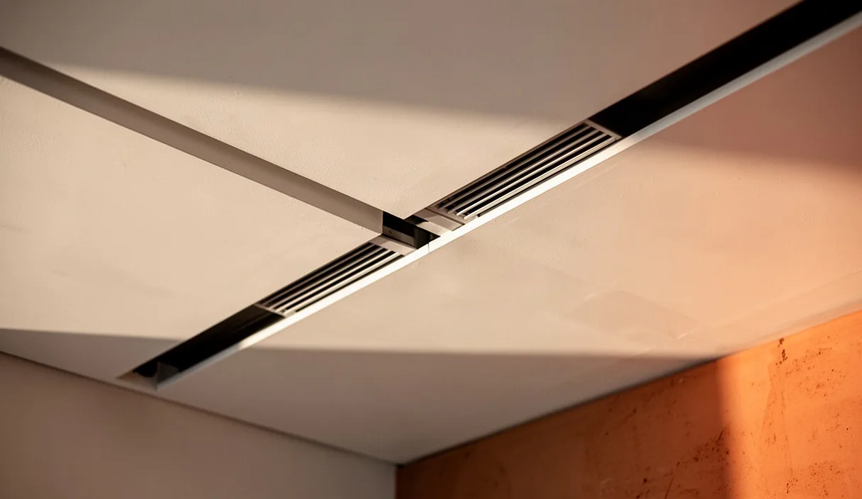
The ceiling plane remains the most contested surface in commercial interior architecture, subject to competing claims from structural engineers, lighting designers, and acousticians. Among these demands, air distribution is frequently reduced to an afterthought, resolved with stamped sheet-metal grilles that disrupt monolithic surfaces or compromised linear runs placed solely for visual alignment. A linear slot diffuser, however, is not a decorative reveal that happens to pass conditioned air; it is an aerodynamic nozzle designed to entrain room air through disciplined boundary-layer physics while maintaining stable interior thermal gradients.
When specified correctly, linear diffusers remain visually quiet while discharging high air volumes without draft or audible turbulence. Achieving this equilibrium demands strict adherence to duct geometry, boundary physics, framing tolerances, and commissioning protocols. The failure of any single component, whether an undersized plenum collar or an uneven drywall mud flange, converts a sophisticated terminal device into an acoustic nuisance or a vector for interstitial condensation.
Aerodynamics of Linear Slot Air Patterns and Throw Distances
The operational logic of a linear slot diffuser depends on the Coanda effect, the physical tendency of a fluid jet to adhere to an adjacent flat surface. When primary air discharges horizontally from a slot mounted flush to a finished ceiling, ambient room air is evacuated along the ceiling interface. This evacuation creates a localized localized low-pressure zone between the air stream and the ceiling plane, pulling the jet upward and holding it against the surface. As the jet travels, it entrains room air at ratios ranging from 12:1 to 20:1, decelerating and equalizing in temperature before dropping gently into the occupied zone below the 1.8-meter line.
Slot width dictates jet stability and penetration depth. Standard commercial linear slots are manufactured in nominal apertures of 13 mm, 19 mm, 25 mm, and occasionally 32 mm. A narrower 13 mm slot accelerates the discharge air, generating high shear forces that enhance induction, which proves useful in cooling applications with high sensible heat loads. However, if the discharge velocity exceeds 4.2 meters per second, the jet generates high-frequency hiss, while a velocity below 1.8 meters per second causes the stream to detach prematurely from the ceiling, dumping cold air directly onto occupants.
Throw distance is typically cataloged at terminal velocities of 0.75, 0.50, and 0.25 meters per second. For cooling configurations, the horizontal throw must span approximately 75 percent to 85 percent of the distance to the nearest opposing air jet or interior wall boundary. If throws from opposing linear diffusers collide at velocities above 0.35 meters per second, the colliding streams redirect downward, creating a persistent draft. Conversely, when linear slots are deployed for perimeter heating along glazed facades, internal pattern controllers must be manually adjusted downward to direct a vertical curtain of air along the glass, overcoming natural thermal buoyancy without washing the glazing so violently that envelope conductive losses increase.
Plenum Box Sizing and Internal Acoustic Insulation
A linear diffuser cannot function predictably without an engineered plenum box. Direct connection of round flexible ductwork to the neck of a linear diffuser creates extreme localized velocities and asymmetrical throw patterns. The plenum acts as an expansion chamber, converting high-velocity dynamic pressure from the duct into uniform static pressure along the entire length of the active discharge slots.
The internal cross-sectional area of the plenum should be sized so that internal air velocity does not exceed 2.2 meters per second. Sizing the plenum to this velocity ensures that static pressure remains uniform across the slot length, preventing the common defect where the end nearest the duct inlet discharges at twice the velocity of the far end. Side-entry round collars should have a diameter at least 25 mm smaller than the total plenum height to avoid turbulence along the top plate. If ceiling void constraints necessitate an oblong or oval collar, the aspect ratio must not exceed 3:1.
Acoustic performance within the plenum requires internal attenuation lining. Specifiers typically select between two insulation profiles depending on project hygiene and sound absorption demands:
- Dual-Density Mineral Fiber (25 mm to 38 mm): Offers superior low-frequency absorption between 250 Hz and 500 Hz. The facing must be coated with a black neoprene compound or factory-applied glass tissue to prevent particulate erosion at velocities up to 10 meters per second.
- Closed-Cell Elastomeric Foam (12 mm to 19 mm): Preferred in healthcare and cleanroom facilities where fiber migration is unacceptable. While its noise reduction coefficient is lower across mid-band frequencies, its non-porous structure resists microbial growth and prevents vapor transmission.
To eliminate cross-talk between adjacent executive suites served by a continuous linear visual profile, the plenum must be physically compartmentalized. Internal acoustic baffles constructed from 1.2 mm galvanized sheet steel lined on both faces with dense acoustic insulation should be placed exactly over demising wall partitions, backed with acoustic sealant to preserve partition STC ratings.
Drywall Framing Details for Trimless Architectural Integration
Flangeless or "mud-in" linear diffusers allow the architectural aperture to read as a crisp, continuous void within gypsum board ceilings. However, these installations are susceptible to hairline perimeter cracking if structural movements and thermal shifts are not accommodated by framing detailing.
Heavy-gauge steel studs (minimum 0.9 mm base metal thickness) must frame the opening continuously on all four sides. The diffuser housing should not depend on the drywall panel for dead-load support; it must be suspended independently from the primary soffit using rigid threaded rods or heavy-gauge galvanized hanger wire with turnbuckles. Suspending the plenum independently isolates the finished ceiling grid from the ductwork mass and vibration generated by central air-handling plants.
Installation requires precise coordination between the mechanical contractor and the drywall sub-contractor. The sequence must proceed as follows:
- Mount the plenum box to structural drop rods, leveling the lower edge precisely to the intended underside of the ceiling framing.
- Secure secondary framing channels parallel to the plenum flange, leaving a continuous 6 mm expansion reveal to isolate ceiling deflection.
- Fasten gypsum board (typically 12.7 mm or 15.9 mm Type X) directly to the framing, tucking the board edge flush against the extrusion shoulder of the diffuser.
- Affix the perforated aluminum mud flange to the drywall surface using low-profile countersunk screws spaced no further than 200 mm on center.
- Apply continuous fiberglass mesh tape across the perforated flange and feather high-strength setting-type joint compound over three successive applications, extending the final coat at least 250 mm onto the drywall field.
To prevent unsightly rust or joint compound discoloration, all mechanical fasteners securing the aluminum trim must be stainless steel or zinc-dichromate coated. Joint compound must support at least 72 hours before HVAC systems are operated; running warm or dehumidified air through the diffusers prematurely accelerates compound drying, leading to shrinkage cracks along the extrusion boundary.
Noise Criteria Benchmarks for Private and Executive Spaces
In high-specification commercial environments such as corporate boardrooms, legal arbitration spaces, and private executive offices, background mechanical noise must sit between NC-25 and NC-30. In open-plan workspaces, targets shift upward to NC-30 through NC-35 to maintain ambient speech privacy without causing acoustic fatigue. Linear slot diffusers generate sound primarily through turbulence at the pattern control blades and air separation along the discharge lip.
System designers must balance slot width, slot quantity, and static pressure loss to keep regenerated noise within acceptable limits. Splitting the required air volume across multiple slots reduces the discharge velocity while preserving total cubic meters per hour, keeping the discharge noise low. The table below details standard acoustic and aerodynamic performance metrics for a 1200 mm length diffuser equipped with a fully insulated plenum box:
| Configuration | Airflow (L/s) | Slot Velocity (m/s) | Static Pressure (Pa) | Acoustic Rating |
|---|---|---|---|---|
| 1 Slot, 19 mm | 42 | 2.8 | 18 | NC-22 |
| 1 Slot, 19 mm | 68 | 4.5 | 46 | NC-33 |
| 2 Slots, 19 mm | 85 | 2.8 | 19 | NC-24 |
| 2 Slots, 19 mm | 125 | 4.2 | 42 | NC-34 |
| 3 Slots, 19 mm | 130 | 2.9 | 21 | NC-26 |
| 3 Slots, 19 mm | 180 | 4.0 | 39 | NC-36 |
When engineering for an NC-25 environment, static pressure drop across the diffuser assembly should ideally remain at or below 22 Pa. Once static pressure exceeds 40 Pa, pattern controller dampers produce audible turbulence that no amount of upstream duct silencer treatment can remediate, because the noise is regenerated at the room boundary itself.
Commissioning Checklist for Static Pressure Balancing
Commissioning linear slot systems requires a deliberate sequence to avoid altering aerodynamic profiles during air balancing. Balancing technicians must coordinate with commissioning agents before finished ceilings are handed over to painting crews.
Execute the following procedures in order to certify linear slot performance:
- Inspect Upstream Duct Work: Verify that manual volume balancing dampers are installed in the rigid branch take-offs at least five duct diameters upstream of the plenum inlet collar. Never attempt primary volume balancing using the diffuser integral pattern blades.
- Verify Internal Blade Orientations: Ensure that all horizontal throw directional blades are oriented identically along the entire linear run. Alternating blades left-and-right along a single continuous slot destabilizes the Coanda attachment, resulting in downward air dumps.
- Establish Plenum Static Pressure: Drill a small pressure tap into the side of the plenum box, midway along its length and 50 mm above the neck. Insert an inclined manometer or calibrated digital micromanometer probe to measure operating static pressure under full-load fan conditions.
- Conduct Multi-Point Traverse Measurements: Measure air discharge using a calibrated velocity hood fitted with a dedicated narrow-slot linear adapter. If using a thermal anemometer, take readings at 150 mm increments along the slot length, positioning the probe precisely in the plane of the discharge vena contracta.
- Seal Test Ports: Remove static pressure probes and seal all test access holes with airtight silicone plugs or mastic tape rated to UL 181 standards.
If commissioning measurements indicate an air velocity variation greater than 15 percent along a contiguous 2.4-meter linear run, the inlet collar is generating an uneven velocity profile. In such instances, install a perforated distribution baffle inside the plenum chamber directly downstream of the collar rather than pinching the manual volume damper at the branch, which merely increases system pressure drop.
Common Mistakes
The most pervasive error in architectural ceiling design is using the linear diffuser pattern blades as system balancing dampers. Restricting airflow directly at the diffuser face generates localized static pressure spikes, transforming an otherwise quiet NC-25 terminal into a high-frequency whistle that registers well above NC-38.
Another persistent failure occurs when specifying continuous visual runs that traverse conditioned perimeter zones and unconditioned partition cavities. If continuous slot extrusions pass through demising partitions without absolute physical barriers inside both the plenum and the diffuser channel, conditioned air bypasses the room envelope. This allows noise, smoke, and air pressure to leak between secure tenancies.
Neglecting condensation control on chilled air installations can lead to severe moisture issues. In humid climates, when cold air (12 to 14 degrees Celsius) passes through a non-thermally broken aluminum diffuser body, the outer flange temperature can fall below the ceiling void dew point. Moisture then condenses directly on the drywall interface, leading to mold growth and plaster degradation. In these environments, specify extrusions with integral thermal breaks or wrap the external plenum and flange boundaries with vapor-sealed closed-cell elastomeric insulation.
Practical Next Steps
To implement linear slot air systems successfully, design teams must reconcile geometric clearances with MEP loads during the early stages of spatial coordination. The mechanical engineer must calculate the cubic meters per hour required per linear meter, selecting slot counts and widths based on an internal plenum velocity target of 2.0 to 2.2 meters per second.
Next, structural clearances in the ceiling void must be validated against the specified plenum heights. A typical 2-slot, 19 mm system with a 200 mm side inlet requires at least 320 mm of clear space above the finished ceiling grid to maintain correct approach geometry. Where slab-to-ceiling clearances are constrained, specify custom top-inlet plenums fitted with internal distribution plates, or split the run into multiple shorter plenums fed in parallel.
Finally, mandate a full on-site visual and acoustic mock-up spanning at least 2.4 meters, incorporating the actual drywall framing, mud-in flanges, specified insulation, and final paint finish. Testing this physical section under balancing air pressures before drywall installation begins ensures that aerodynamic noise, structural deflection, and installation methods are verified prior to construction across the broader floorplate.